Community-built robots you can build, run, and own
 Mobile Robots
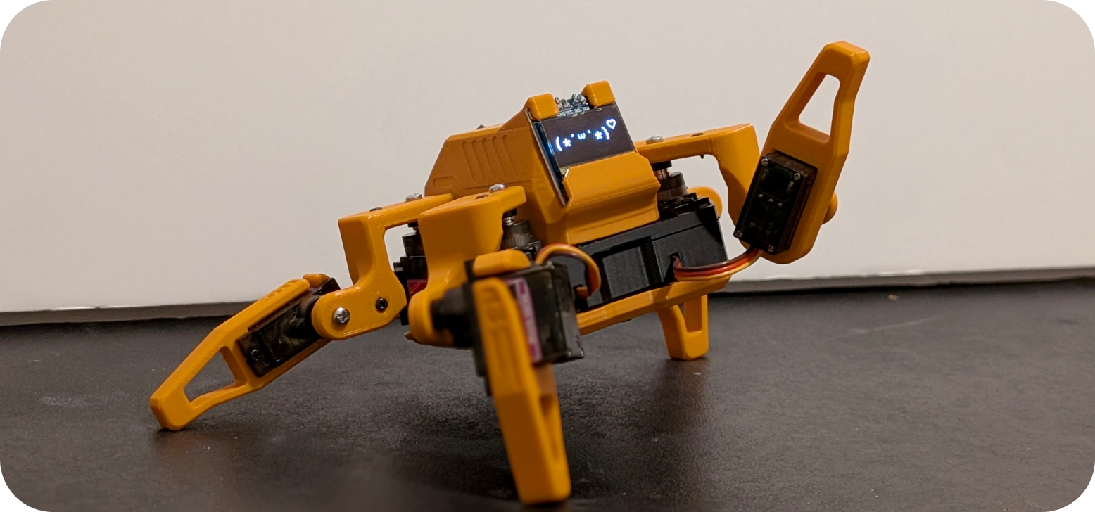
Sesame Quadruped
1,619 stars on GitHub. Sesame is an affordable, open-source mini quadruped robot powered by an ESP32 microcontroller. Designed by Dorian Borian, Sesame uses 8 MG90S metal-gear servos (two per leg) for 8-DOF locomotion and features a 128×64 OLED display that serves as an expressive robot face. Source: https://github.com/dorianborian/sesame-robot All mechanical parts are fully 3D-printable on a standard FDM printer. The hardware folder contains both parametric STEP and Fusion 360 source models alongside the STL files, allowing full customization. The frame, internal structure, covers, and leg segments are all available as individual STLs. The ESP32 firmware handles inverse kinematics, face animations on the OLED display, and a WiFi-based control interface accessible from any browser. A desktop companion app (Sesame Studio) is included for easy gait configuration and pose tuning without writing code. Community documentation covers full assembly with detailed wiring diagrams and a comprehensive BOM. Hat variants are available (enclosed, open, cat ears) for personality customization. With over 1600 GitHub stars, Sesame has become a go-to beginner quadruped platform. License: Apache 2.0.
from $85🛠 BoM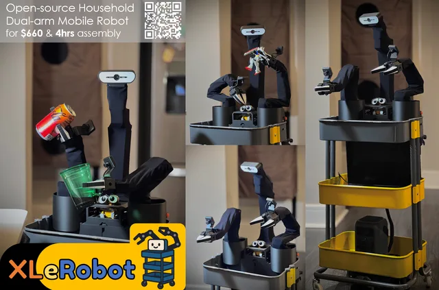 Mobile Robots
XLeRobot Dual-Arm Mobile Home Robot
Low-cost dual-arm mobile robot for embodied AI and household manipulation
from $660🛠 BoM Mobile Robots
LeRobot Humanoid (Biped Platform)
The LeRobot Humanoid (Biped Platform) is a fully open-source, 3D-printed humanoid biped robot developed by Virgile Batto and the Hugging Face LeRobot team. Powered by a Raspberry Pi 5 and 12 RobStride CAN-FD actuators arranged across two legs (6 degrees of freedom per leg, 12 DOF total), it represents a serious open-hardware effort to make capable humanoid locomotion accessible to researchers and advanced builders worldwide. Every mechanical, electrical, and firmware artifact is freely available under the Apache 2.0 license, from the Onshape CAD source to the bill of materials to the motor commissioning scripts. Creator & License Author: Virgile Batto — virgilebatto@gmail.com (Hugging Face LeRobot team) License: Apache 2.0 Hardware repository (CAD, BOM, assembly docs, STLs): https://github.com/Virgileboat/lerobot-humanoid-hardware Runtime repository (motor control, gait, model inference): https://github.com/Virgileboat/lerobot-humanoid-runtime Public Onshape CAD document (start here for design exploration): https://cad.onshape.com/documents/fb645318a27646d1d8840be6/w/d1cae8805fb652b4d1614997/e/804a1da43f242001a05129b4 All build assets — STL files, BOM CSVs, wiring diagrams, motor commissioning scripts — are republished here under the same Apache 2.0 terms. Credit and star the upstream repos if this helps your project. Hardware Requirements This robot is BYOD (Bring Your Own Device). The orobot-firmware layer does not currently support RobStride CAN-FD actuators; all joint control runs directly on the Raspberry Pi through the lerobot-humanoid-runtime repository. The orobot program record here serves as a build reference, asset hub, and control-interface stub. Required hardware: Raspberry Pi 5 (8 GB recommended) — primary compute SAVVYCANFD 2CH CAN-FD adapter (USB, dual channel, 12 Mbps max) — connects Pi to motor bus 12 × RobStride actuators: 2 × RobStride O0 (torso/hip yaw) 2 × RobStride O2 (hip Z) 4 × RobStride O3 (thigh) 4 × RobStride O5 (shin) IMU: BNO055 or BNO085 breakout board Mechanical: ~75 custom 3D-printed PLA+ parts, plus precision bearings and fasteners per BOM Specifications | Parameter | Value | |-----------|-------| | Degrees of freedom | 12 (6 per leg) | | Actuators | 12 × RobStride (CAN-FD) | | Estimated print weight | ~3–4 kg PLA+ | | Estimated total cost | ~$2,636 USD | | Skill level | Advanced | | Build time | Multi-week (motor commissioning → print → assembly → wiring → bring-up) | | CAD source | Onshape (public, link above) | | Control protocol | RobStride CAN-FD over USB adapter | Build Start Sequence Follow this preferred order for a new build: 1. Order all buy parts from first — long-lead items (motors, bearings, shoulder screws) can take weeks. 2. Print all required STL parts per the printing guide at (target 3–4 kg PLA+; orientation matters for structural leg parts). 3. Commission and check every motor before assembly: Follow Run Do NOT start mechanical assembly before protocol/ID commissioning and a motion check on every actuator. 4. Assemble mechanical subassemblies using . 5. Run wiring and first power-on checks: Follow then Validate wiring continuity before connecting high-current source; use a current-limited bench supply for initial checks. Safety > A physical emergency power cutoff (E-stop) is required — keep it accessible at all times during powered operation. Key rules from : Bring up logic power before actuator power. Confirm CAN heartbeat and watchdog behavior before enabling torque. Enable actuators only after joint limit and zero-position checks pass. Never run the robot unattended during first powered-motion passes. Keep clear of moving joints during bring-up; RobStride motors deliver significant torque. Do not start mechanical assembly before motor commissioning is complete — protocol or ID errors after assembly require disassembling the leg to fix. Attribution This program page was created by the orobot BROKER-2 index to help builders find and start this project. All design credit goes to Virgile Batto and the Hugging Face LeRobot team. If this build helps you, please star the source repos and reach out to the creator directly at virgilebatto@gmail.com. The humanoid robotics community grows when open hardware gets the recognition it deserves.
from $2636🛠 BoM Mobile Robots
Hexapod
Hexapod — 3D Printed Six-Legged Walking Robot A fully 3D-printed hexapod robot with 18 servo motors (three per leg) providing lifelike, agile locomotion. Designed by rookidroid.com, this project uses either an ESP32 or Raspberry Pi Pico W/2W controller board with built-in WiFi for wireless remote control. The firmware supports over-the-air (OTA) updates so you can iterate on motion patterns without touching the hardware. Hexapod v2 is the recommended build. The original v1 used MG90S servos which are prone to failure; v2 upgrades to stronger 21G DS Power/Miuzei servos and is significantly more reliable. Specifications | Property | Value | |----------|-------| | Legs | 6 | | Servos | 18 x 21G (3 per leg: hip, knee, ankle) | | Controller | ESP32 or Raspberry Pi Pico W/2W | | Communication | WiFi (UDP port 1234) + OTA updates | | Power | 2 x 18650 Li-ion cells | | Print time | ~40-60 hours total (no supports needed) | | Skill level | Intermediate | Motion Modes The ESP32 firmware implements a pre-computed look-up-table gait system with 18 motion modes including: directional walking at 0, 45, 90, 135 degrees (left and right variants), 180 degrees; fast forward and backward; turn left and right; climb forward and backward; body rotations on X, Y, Z axes; and a twist mode. Bill of Materials | Item | Qty | Notes | |------|-----|-------| | 21G servo (DS Power or Miuzei) | 18 | Main actuators | | Hexapod controller board (ESP32 or Pico version) | 1 | From rookidroid.com | | 18650 Li-ion battery | 2 | | | 18650 battery holder | 1 | | | Rocker switch | 1 | | | M2 x 6mm screws | 36 | | | M2 x 10mm screws | 198 | | | M2 nuts | 234 | | | M4 x 6mm pins (304 steel) | 18 | | | MR74-2RS bearings (4x7x2.5mm) | 18 | Leg joints | 3D-Printed Parts All parts print without supports. The full set covers: body (9 unique parts), joints (3 types, 6 sets), legs (3 types, 6 sets), feet (4 types, 6 sets), and a cable-holder accessory — 20 unique STL files, all included here. Attribution Creator: rookidroid.com Source: https://github.com/rookidroid/hexapod License: GNU GPL v3
from $120🛠 BoM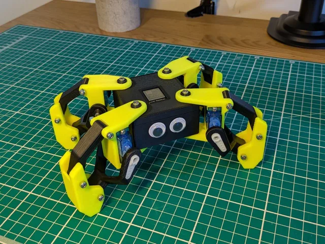 Mobile Robots
Kame32
Kame32 is an open-source quadruped walking robot by JavierIH. Built around an ESP32 and 8 servo motors, it walks, runs, dances, and performs a rich library of quadruped gaits — all controlled wirelessly via a built-in web-based gamepad over Wi-Fi. All structural parts are 3D-printable. A custom PCB (KiCAD gerbers included) centralizes servo wiring. Choose MG90S (higher torque) or SG90 servos — brackets for both variants are included. Specifications | Property | Value | |----------|-------| | Motors | 8 servos (MG90S or SG90) | | DOF | 8 (2 per leg) | | Controller | ESP32 Dev Kit | | Control | Web gamepad via Wi-Fi | | PCB | Custom KiCAD design (gerbers included) | | CAD | FreeCAD source file | | Build time | 1–2 weekends | | Skill level | Intermediate | Gaits Walk · Backward · Run · Omni Walk · Turn Left · Turn Right · Moonwalk · Dance · Up/Down · Push Up · Hello · Jump · Home All gaits use the Octosnake oscillator library — sinusoidal servo control with per-axis phase offsets. Hardware ESP32 drives 8 PWM servos at 50 Hz / 16-bit resolution on GPIO 5, 18, 19, 21, 25, 26, 32, 33. Per-servo calibration offsets stored in ESP32 NVS. Firmware PlatformIO / Arduino. Build environments: calibration (tune offsets) and gamepad (web UI controller). Attribution Creator: JavierIH Source: github.com/javierih/kame32 License: CC BY-SA 4.0 (hardware) - GPL-3.0 (code) Build Guide Source repository with CAD, firmware, and assembly files: github.com/JavierIH/Kame32 Build Guide Source repository with CAD, firmware, and assembly files: github.com/JavierIH/Kame32
from $50🛠 BoM Mobile Robots
Yertle Quadruped
Yertle — A 3D Printed Quadrupedal Robot for Locomotion Research Yertle is a 12-DOF quadruped robot designed for locomotion research. It fuses the leg geometry of the Kangal quadruped with the body geometry of SpotMicro, making most parts cross-compatible with the SpotMicro ecosystem. Source: https://github.com/Jerome-Graves/yertle Creator: Jerome Alexander Graves License: MIT Status: Work-in-progress (functional; ROS2 integration pending) This Program is a learning entry point. The original firmware is C++ on an ESP32 with a Python GUI master controller — the orobot Program here exposes a stubbed JavaScript interface so you can explore the gait/command surface in-browser. To run on real hardware, follow the upstream build and flash instructions. Mechanical 4 legs × 3 DOF (hip yaw + hip pitch + knee) = 12 servos total Leg extension: ~20 cm Mass: ~1.8 kg Frame: PLA or ABS, printable on a 150 × 150 mm bed (Ender 3 Pro tested) Print time: ~2 weeks (5–10 h/day on a single Ender 3 Pro) Electronics | Role | Component | |---|---| | Microcontroller (master of servos/sensors) | ESP32s | | Optional onboard SBC (vision/ROS) | Raspberry Pi 4B | | Servo driver | PCA9685 (16-channel PWM) | | Servos × 12 | SPT5435LV-180W, 35 kg·cm waterproof digital (≥ 15 kg·cm required) | | IMU (optional) | MPU9250 9-axis | | Battery | 7.4 V 2S 5000 mAh LiPo (~30 min runtime) | | Power | SBEC 6 V 20 A | The robot can run headless from the ESP32 alone (UDP-over-WiFi to a Python GUI on a laptop/phone) or with a Pi4 onboard for vision and ROS. Software architecture Master/slave over serial or UDP/WiFi: Slave (ESP32, C++/Arduino): servo control, sensor read, inverse kinematics, safety limits. Master (Python 3 GUI): gait generation, sensor fusion, ROS2 (todo). Runs on anything with WiFi + screen + Python 3. Simulation: Python-based built-in simulator; URDF available for Gazebo/Unity. Build cost ~£250 total (servos dominate at ~£162). See full BOM in the upstream Design/README. 3D printed parts (21 STLs) Shell (4): Top, Bottom, Front, Back Frame (9): Inner/Outer/Upper/Lower Shoulder Frame, Left/Right Servo Mount, Servo Mount Top Bracket, Side Body Beam, Electronics Mounting Plate Legs (8): Inner/Outer Tibia, Femur, Femur Servo Connector, Left/Right Shoulder, Short Link, Long Link All STLs: https://github.com/Jerome-Graves/yertle/tree/main/Design/STL Hardware compatibility (BYOD) Yertle is not an orobot-firmware-native build. It uses a custom ESP32 firmware. Running the orobot Program against real hardware requires bridging the orobot WebSocket protocol to Yertle's UDP master/slave protocol — a custom integration tracked under the orobot ESP32 BYOD effort. Inspirations Kangal (leg design) SpotMicro (body geometry, parts compatibility) Open Quadruped --- Extracted from commit on 2026-04-27.
from $350🛠 BoM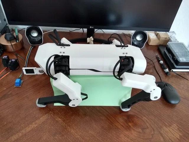 Mobile Robots
SpotMicro ESP32
377 stars on GitHub. SpotMicroESP32 is Michael Kubina's redesign of the SpotMicro quadruped, derived from KDY0523's original Thingiverse design, optimized for support-free 3D-printing and built around an ESP32-DevKitC. 12-DOF (3 servos per leg). Source: https://github.com/michaelkubina/SpotMicroESP32 Hardware: 12 servos (3 per leg: shoulder yaw, upper, lower) ESP32-DevKitC main controller Optional ESP32-CAM for vision LiPo battery with custom mounting brackets Software ecosystem (community forks): Maarten Weyn BLE/IK firmware: https://github.com/maartenweyn/SpotMicro_ESP32 Blacksheep Nitro Fork (PCB + walking gait + RC): https://github.com/Blacksheep909/SpotMicroESP32-Nitro-Fork SpotMicro-Leika (FreeRTOS + 2 gaits): https://github.com/runeharlyk/SpotMicroESP32-Leika SpotMicroAI Community: https://spotmicroai.readthedocs.io/ Resources: Thingiverse: https://www.thingiverse.com/thing:4559827 Original SpotMicro by KDY0523: https://www.thingiverse.com/thing:3445283
from $130🛠 BoM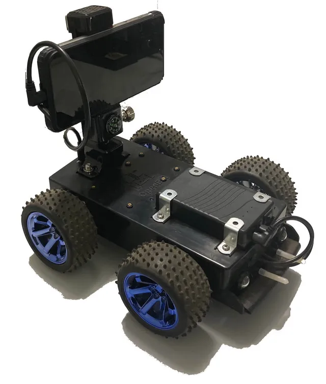 Mobile Robots
OpenBot
3,262 stars on GitHub. OpenBot turns your smartphone into the brain of a low-cost robot, democratizing autonomous robotics for anyone with a ~$50 budget. Developed at Intel Labs and the Technical University of Munich, OpenBot is an MIT-licensed platform designed to make AI-powered robotics accessible to researchers, students, and hobbyists worldwide. Source: https://github.com/isl-org/OpenBot The robot body is a 3D-printed differential-drive chassis that holds two gear motors, a speed controller, and a custom PCB — all controlled by an Arduino Nano. The Android or iOS smartphone docks on top, providing the camera, CPU, and network stack. The pairing eliminates the need for a dedicated compute board: your phone's neural engine runs person-following, autonomous navigation, and custom AI policies trained using the companion mobile app. Four body variants are included: the standard regularbody (two-part top/bottom), the blockbody designed for a PCB stack, the gluebody for simpler assembly without screws, and the slimbody for narrower builds. A universal phonemount adapter fits any of the variants. The 12-part printable set covers bodybottom and bodytop for the regular variant, blockbodybottom and blockbodytop, gluebodybottomA/B and gluebodytopA/B with glue connector halves, slimbodybottom and slimbodytop, and the phonemountbottom/top. The project also supports a tank variant, an MTV off-road variant, and an RTR (ready-to-run) version based on an RC chassis. License: MIT. --- Install Notes OpenBot's intelligence lives in the Android app** — vision, navigation, data collection, and AI inference all run on the phone. The orobot device code only bridges the Arduino Nano motor controller layer (forward/backward/turn via serial JSON). Higher-level behaviors (person following, autopilot, data recording) require the OpenBot Android or iOS app connected to the Arduino via USB OTG cable. The orobot integration is useful for basic motor testing and manual drive, but does not replicate the full OpenBot feature set.
from $50🛠 BoM Mobile Robots
mjbots Hoverbot
57 stars on GitHub. The mjbots Hoverbot is a compact wheeled robot built around surplus hoverboard hub motors, designed for outdoor and semi-rugged terrain navigation. Developed by Josh Pieper of mjbots, it demonstrates how powerful consumer-grade hub motors combined with custom motor control electronics can produce a capable autonomous platform. Source: https://github.com/mjbots/hoverbot The robot uses two hoverboard hub motors driven by mjbots moteus-c1 brushless motor controllers — high-performance FOC controllers with integrated CAN-FD communication. An mjbots pi3hat provides IMU (gyro + accelerometer) fusion and CAN-FD bus aggregation. A Raspberry Pi 4 runs the control software, connected to the motor controllers over CAN-FD for real-time torque and velocity commands. Power comes from a cordless drill battery mounted in a custom 3D-printed battery housing with proper mechanical retention rails. The 18V battery drives the 36V-rated hoverboard motors at a reduced voltage, limiting top speed to ~2 m/s — faster than walking pace but mechanically safe. The robot can operate for hours on a single charge and handles varied terrain including grass, gravel, and uneven pavement. The entire chassis is 3D-printable in PETG, with M3 and M2.5 heat-set inserts providing structural joints. An optional GoPro mount allows first-person video capture. The design is fully open-source with all STL files, source code, and configuration published under Apache 2.0. Hardware includes: Raspberry Pi 4 (2GB), 2× mjbots moteus-c1 motor controllers, mjbots pi3hat (IMU + CAN-FD), mjbots power_dist module, 2× surplus hoverboard hub motors, 18V cordless drill battery, 3D-printed PETG chassis.
from $500🛠 BoM Mobile Robots
LeKiwi Mobile Base
LeKiwi — Mobile Base for SO-ARM100 LeKiwi is a three-wheeled omnidirectional mobile base designed to carry the SO-ARM100 (or its sibling Koch arm) around a real environment. Add a 5-DOF teleop arm on top, put a camera on the base and the wrist, and you have a low-cost mobile manipulation platform compatible with the entire LeRobot stack. Why "kiwi"? Kiwi drive — three omniwheels at 120° — gives you true holonomic motion: the base can translate in any direction and rotate independently, no slewing required. That's huge for teleop demos where a human operator is driving with a joystick and expects the base to move "like a spaceship," not like a car. What you get Three-wheel kiwi drive with omniwheels on custom-printed hubs Feetech or Dynamixel servo variants (pick your servo ecosystem — both hubs are included) Raspberry Pi + optional Jetson Orin compute cage printed onto the base plate Battery compartment sized for standard 3S/4S LiPo packs Servo-controller mount and base-mounted webcam holder Mounting pattern on the top plate that drops directly into an SO-ARM100 base What you do with it Mobile teleoperation: leader arm drives the follower arm, joystick drives the base. Stream both from a laptop anywhere on the network. Mobile imitation learning: extend LeRobot's episode recorder to include base velocities. The existing Diffusion Policy and ACT models have been adapted by the community to condition on base state. Multi-camera observation: base camera sees the environment, wrist camera sees the task. Both go into the policy. Classroom mobile robotics: cheap, printable, and works with commodity servos. Parts ~12 canonical printed parts on the base: / — sandwich plate structure — servo bracket, ×3 at 120° — attaches the omniwheel to the servo horn, ×3 — LiPo tray / — Raspberry Pi 5 enclosure — optional Jetson Orin bracket — Dynamixel U2D2 / Waveshare bus driver holder , — webcam rigs — replacement SO-ARM100 base shim that lets the arm sit flush on the base plate Attribution & license Designer: SIGRobotics-UIUC (Student Interest Group on Robotics, University of Illinois Urbana-Champaign) Upstream: https://github.com/SIGRobotics-UIUC/LeKiwi License: Apache 2.0 Ecosystem: LeRobot Links Upstream repo: https://github.com/SIGRobotics-UIUC/LeKiwi SO-ARM100 (arm to mount on top): https://github.com/TheRobotStudio/SO-ARM100 LeRobot stack: https://github.com/huggingface/lerobot Build Guide Step-by-step assembly guide: github.com/SIGRobotics-UIUC/LeKiwi/blob/main/Assembly.md
from $450🛠 BoM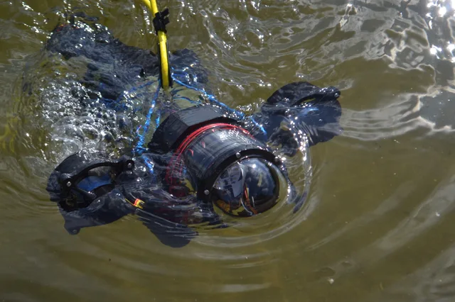 Mobile Robots
Underwater Drone
75 stars on GitHub. This open-source customisable underwater drone is a 3D-printable submersible robot designed by Guido and Fabio Schillaci at Humboldt-Universität zu Berlin. Published as an arXiv preprint, the design enables multiple propeller and thruster configurations for varying research and exploration tasks. Source: https://github.com/guidoschillaci/underwater-drone The drone is built around the 4" watertight enclosure sold by BlueRobotics, providing a waterproof housing for electronics. Thrusters use Turnigy Aerodrive DST brushless motors (tested with DST-700 and DST-1200 variants) inspired by the BlueRobotics thruster design. All 18 structural components are 3D-printable and recommended to be printed with solid infill for watertight structural integrity. Key printable components include: main thruster body, motor mount, thruster cap, propeller, ballast cylinder, ballast cap, anterior and posterior clamps (superior and inferior variants), adapters (90-degree, round male/female, split), a 2-tube connector, rear clamp connector, and a stiffening stick. The modular clamp system allows configuring the drone for different mission profiles — forward-facing cameras, lateral thrusters, ballast placement, or instrument mounting. Applications include aquatic research, underwater exploration, coral reef monitoring, and educational robotics. License: Creative Commons Attribution 4.0 International (CC-BY 4.0). --- Install Notes This repository contains CAD files and assembly instructions for a 3D-printable submersible — there is no firmware or control software included. The design is intended for custom electronics integration. The orobot Program code is a reference stub only. To build a controllable version, you will need to design or source your own motor controller and connect it via serial or WiFi. Build Guide 3D models, build instructions, and configuration details: github.com/guidoschillaci/underwater-drone
from $1050🛠 BoM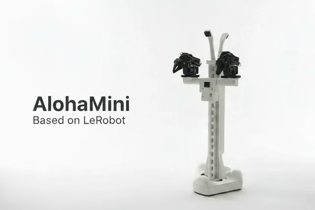 Mobile Robots
AlohaMini Dual-Arm Mobile
AlohaMini — Dual-Arm Mobile Manipulation Platform A miniaturized Aloha-style dual-arm mobile platform with a motorized vertical lift column. Two SO-ARM101 follower arms sit on a shared lift tower mounted to a three-wheel omni base, giving the platform a tabletop-to-floor reach envelope that makes real household-scale manipulation possible at hobbyist cost. What makes AlohaMini distinctive Most DIY bi-manual mobile bases have one big gap: they're too short. An SO-ARM on a fixed 20-cm pedestal can't pick up something on the floor or reach a countertop — the workspace is stuck at one height. AlohaMini solves this with a powered vertical lift that raises both arms together, scanning the full vertical reach of a human workspace. Paired with: Two SO-ARM101 follower arms (leader arms for teleop are also included in the STL set) A three-omniwheel kiwi drive base (bearing-mounted axles, printed chassis) Seeed Studio XIAO + WaveShare Dynamixel bus driver mounts Camera wrist mounts on both arms What you can do with it Imitation learning at floor and table height — record bimanual episodes where the arms need to descend to grab something off the floor, then lift to place it on a surface. Mobile bimanual teleop — pair with two leader arms (also in the STL set) to drive both follower arms plus the base from a single operator. VLA training data collection — the shared base frame + lift + dual arms is close to the canonical "robot" embodiment used in recent VLA papers (RT-2, OpenVLA). Household tasks — clearing a dining table, loading a dishwasher, or picking laundry off the floor — all things a fixed-height arm can't attempt. Printed parts (this program) Arms (D/F/L prefix): — shared base that ties the arms to the lift/base , — arm link structure , — joint assemblies — follower gripper jaw , — leader arm handle + trigger Mobile base (OB prefix): — side structure — drive servo brackets , — drivetrain hardware The full repo has ~60 STLs covering the lift column parts, battery tray, and VR controller teleop handles. Attribution & license Designer: Yi-Teng Li (liyiteng) Upstream: https://github.com/liyiteng/AlohaMini License: Apache 2.0 Built on: SO-ARM101, LeKiwi base geometry, and the ALOHA/ALOHA2 dual-arm research lineage from Stanford Links Upstream: https://github.com/liyiteng/AlohaMini LeRobot: https://github.com/huggingface/lerobot ALOHA paper: https://tonyzhaozh.github.io/aloha/ Build Guide Hardware assembly guide (BOM, wiring, mechanical assembly): github.com/liyiteng/AlohaMini/blob/main/docs/hardwareassembly.md
from $750🛠 BoMBrowse by type