3D Print Open Source AI Robots
 Mobile Robots
Solo12 Quadruped
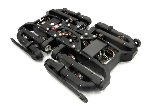
$5000Solo12 is an open-source 12-DOF quadruped robot from the Open Dynamic Robot Initiative (ODRI), a collaboration between MIT, LAAS-CNRS, NYU, and MPI-IS to provide the legged-locomotion research community with an affordable, reproducible platform for dynamic control research. The robot has four legs, each with three degrees of freedom (hip abduction/adduction, hip flexion/extension, and knee), actuated by ODRI's open-source brushless direct-drive actuator modules. Direct-drive transmissions give the robot high-bandwidth torque control and transparent dynamics — critical for whole-body MPC, reinforcement learning, and contact-rich locomotion experiments that are difficult or impossible on geared quadrupeds. Solo12 has been used in dozens of published locomotion papers studying bounding gaits, stair climbing, reactive balance control, sim-to-real reinforcement learning, and model-predictive control. The full hardware and software stack — actuator PCBs, mechanical CAD, master board firmware, real-time control interface, and Pinocchio-based dynamics — is published under BSD-3-Clause, making Solo12 one of the most accessible research-grade quadrupeds available. This program provides cloud-side locomotion commands (stand, sit, directional walking, trot, emergency stop) that relay to the onboard controller over WebSocket. The hardware requirement is a Raspberry Pi 4 acting as the high-level controller; the real-time low-level control loop runs on the master board over EtherCAT/SPI to the 12 actuator modules. Credit to the Open Dynamic Robot Initiative consortium (LAAS-CNRS, MPI-IS, NYU, MIT) — upstream repository at https://github.com/open-dynamic-robot-initiative/openrobotactuatorhardware under BSD-3-Clause. Build Guide Step-by-step assembly instructions for the Solo12 quadruped: Solo12 hardware README Printing Solo12 is a research-grade direct-drive quadruped — most of the robot is custom electronics, machined aluminium, and ODRI actuator modules, so the 3D-printed set is intentionally small (this is the correct, complete print set, not a partial one). The 11 parts below are the Solo12-specific printable components, curated from the much larger ODRI repo (which contains 200+ STLs spanning tools, jigs, and other robot configurations). PLA/PETG, ~214 cm³ total. Leg hip modules — print one per corner (4, all distinct): solo12hipfefl (front-left), solo12hipfefr (front-right), solo12hipfehl (hind-left), solo12hipfehr (hind-right) These are the hip flexion/extension housings; each corner is a separate handed part — print all four. Body frame — print one each (5): bodystructurecenter, bodystructureside, bodystructuretopimu (top plate with IMU mount) hipadapter (mounts the hip modules to the body) ledcover (status-LED cover for the NeoPixel ring) Assembly stand (accessory — 2): standfoot and standfork form a benchtop stand/cradle used to hold the robot during assembly and calibration. This is an accessory/jig, not part of the walking robot — print it if you want the stand, skip it otherwise. Not printed: the 12 ODRI brushless direct-drive actuator modules, 6 micro-driver PCBs, master board, IMU, timing belts, bearings, and machined plates are all sourced/fabricated per the BOM — only the parts above are 3D-printed.
 Humanoids
Poppy Humanoid
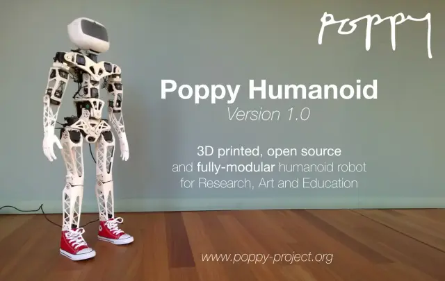
$1050891 stars on GitHub. Poppy Humanoid is an open-source, 3D-printed, 25-DOF humanoid robot from the Poppy Project, originally developed at Inria's Flowers team for research in embodied cognition, human-robot interaction, and robot learning. Standing 84 cm tall and weighing about 3.5 kg, Poppy is designed with biomechanically motivated bent-thigh proportions. Source: https://github.com/poppy-project/poppy-humanoid The robot uses 25× Dynamixel smart servos on a daisy-chained TTL bus. A Raspberry Pi onboard provides high-level control via pypot (the Python Dynamixel library developed for this project), with real-time joint targets streamed from user code. Compliant mode lets you back-drive the robot by hand to teach poses and trajectories — a powerful pedagogical and research primitive. Poppy Humanoid has been used in dozens of published studies on bipedal walking, imitation learning, developmental robotics, and tutor-assisted programming education. Poppy is a modular family: the Torso variant is a desk-mountable upper body, and the Ergo Jr is a 6-DOF desk arm. Both share the Dynamixel bus stack and the pypot API. This means behaviors developed for one Poppy robot often port directly to another with configuration-level changes rather than code rewrites. Hardware interface: USB-to-Dynamixel adapter (U2D2 or USB2AX) connected to the Raspberry Pi. No Arduino required. This program exposes cloud-side endpoints for rest/sit postures, arm waving, compliant-mode toggle, dance primitive playback, and full demonstration record/replay. The Raspberry Pi onboard bridges the orobot cloud to the Dynamixel bus via pypot. Credit to the Poppy Project community and Inria Flowers team (poppy-project.org) — upstream repository at https://github.com/poppy-project/poppy-humanoid. Hardware under Creative Commons Attribution-ShareAlike 4.0 (hardware/LICENSE.md), software under GPLv3 (software/LICENSE). Share-alike requires derivative hardware designs to be published under the same CC-BY-SA-4.0 license. Build Guide Official assembly guide: docs.poppy-project.org Printing This file set contains the structural body meshes for the Poppy Humanoid (head, chest, abdomen, bust/abs/hip motor brackets, and the limb segments: shoulder, forearm, hip, thigh, shin, foot). Poppy is a left/right symmetric biped, so the limb parts are mirror pairs — each l part has a matching r part, and both must be printed (they are not alternates). Important note on completeness: the current list is the curated set of printable body meshes, but it is not yet the full humanoid. Several right-side mirror parts (rshoulder, rhip, rhipmotor, rthigh, rfoot, rshouldermotor) are not present in this list and must be printed as mirrors of their left-side counterparts. The complete, official, print-ready STL package for the full ~25-DOF Poppy Humanoid is distributed by the upstream project as the "STL3Dprintedparts.zip" asset attached to the poppy-project/poppy-humanoid GitHub releases; builders should use that archive for the definitive, complete part list and quantities. Note on file naming: these are the "visual" geometry meshes from Poppy's URDF model. The companion "_respondable" meshes that appear in the source repository are simplified collision hulls used only for physics simulation and should NOT be printed — they have been excluded from this Print All set.
 Mobile Robots
AcroMonk Brachiating Robot
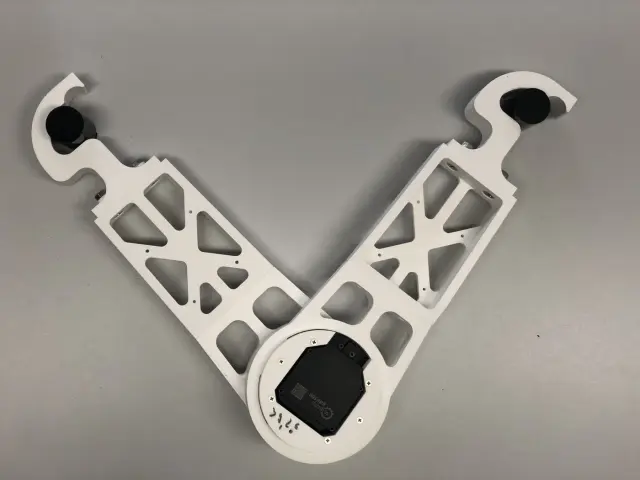
$105054 stars on GitHub. AcroMonk is a minimalist underactuated brachiating robot — it swings hand-over-hand across a horizontal ladder bar using just one quasi-direct drive (QDD) actuator and passive grippers. Published in IEEE Robotics and Automation Letters 2023 (featured in IEEE Spectrum Video Friday), it is the first brachiator with unactuated grippers that can perform more than two consecutive brachiation maneuvers. Source: https://github.com/dfki-ric-underactuated-lab/acromonk The robot is built from a single brushless QDD motor (MIT Cheetah-style), 3D-printed structural links, and simple passive hook grippers that rely on gravity and swing momentum for release and re-grasp. The absence of gripper actuators dramatically simplifies the mechanical design while making the control problem much harder — AcroMonk must time its swing precisely. Control methods include trajectory stabilization via TVLQR (time-varying LQR) and reinforcement learning. A full simulation environment (MuJoCo/PyBullet) is provided alongside hardware controllers. The kit is designed to be an affordable research testbed for underactuated locomotion research. Hardware: 1× quasi-direct drive brushless actuator (MIT Cheetah motor or equivalent), 3D-printed links and gripper hooks, horizontal ladder test bar. Open source under BSD-3-Clause license with accompanying IEEE RA-L paper. Build Guide Hardware build files, BOM, and assembly docs: github.com/dfki-ric-underactuated-lab/acromonk/tree/main/hardware
 Mobile Robots
Underwater Drone
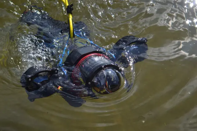
$105075 stars on GitHub. This open-source customisable underwater drone is a 3D-printable submersible robot designed by Guido and Fabio Schillaci at Humboldt-Universitat zu Berlin. Published as an arXiv preprint, the design enables multiple propeller and thruster configurations for varying research and exploration tasks. Source: https://github.com/guidoschillaci/underwater-drone The drone is built around the 4" watertight enclosure sold by BlueRobotics, providing a waterproof housing for electronics. Thrusters use brushless motors (see note below on component versions); all 18 structural components are 3D-printable and recommended to be printed with solid infill for watertight structural integrity. The modular clamp system allows configuring the drone for different mission profiles — forward-facing cameras, lateral thrusters, ballast placement, or instrument mounting. See Print Files for the full list of 18 printable components. Thruster note: the description references Turnigy Aerodrive DST (DST-700/DST-1200) brushless motors; some BOM links point to the ApisQueen 5060 Waterproof Brushless Underwater Motor instead. Verify which motor you are sourcing before purchase — the two are not the same form factor. Applications include aquatic research, underwater exploration, coral reef monitoring, and educational robotics. License: Creative Commons Attribution 4.0 International (CC-BY 4.0). --- Install Notes This repository contains CAD files and assembly instructions for a 3D-printable submersible — there is no firmware or control software included. The design is intended for custom electronics integration. The orobot Program code is a reference stub only. To build a controllable version, you will need to design or source your own motor controller and connect it via serial or WiFi. Build Guide 3D models, build instructions, and configuration details: github.com/guidoschillaci/underwater-drone --- Printing This Print All set maps 1:1 to the upstream folder — all 18 structural components, no sim meshes or duplicates. Print in PETG (hydrolysis-stable) with solid / near-100% infill for watertight structural integrity. Quantities (4-thruster configuration) The drone uses 4 thrusters, so thruster and propeller parts repeat: | Part | Qty | Notes | |------|-----|-------| | thrustermain.stl | 4 | One per thruster | | thrustercap.stl | 4 | One per thruster | | thrustermotormount.stl | 4 | One per thruster | | thrusterdst2bluerovadapter.stl | 4 | Motor-to-housing adapter (one per thruster) | | propeller.stl | 4 | One per thruster (or use motor-matched commercial props per BOM) | | clampanteriorsuperior.stl | 1 | Modular clamp | | clampanteriorinferior.stl | 1 | Modular clamp | | clampposteriorsuperior.stl | 1 | Modular clamp | | clampposteriorinferior.stl | 1 | Modular clamp | | posteriorclamp2tubeconnector.stl | 1 | Clamp-to-tube connector | | rearclampconnector.stl | 1 | Rear clamp connector | | adapter90.stl | 1+ | Tube adapter | | adapterroundmale.stl | 1+ | Tube adapter | | adapterroundfemale.stl | 1+ | Tube adapter | | adaptersplit.stl | 1+ | Tube adapter | | stick.stl | 1+ | Structural rod | | ballastcylinder.stl | 1+ | Ballast tube | | ballastcap.stl | 1+ | Ballast cap | Modular by design: the clamp/adapter/ballast system is meant to be reconfigured for different mission profiles (forward camera, lateral thrusters, ballast placement). Print extra adapters, sticks, and ballast cylinders to suit your chosen layout — the counts above are a baseline for a standard 4-thruster build. Motor note: the upstream design targets Turnigy Aerodrive DST motors (hence ); if you source the ApisQueen 5060 motor listed in some BOM links, the motor-mount fit differs — verify before printing the thruster mounts.
 Mobile Robots
MEVITA Biped
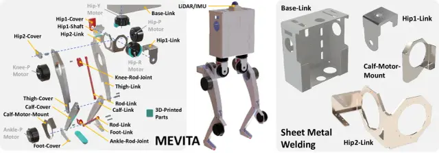
$630090 stars on GitHub. MEVITA is an open-source bipedal robot designed to be assembled entirely from e-commerce components — sheet metal parts, machined elements, and off-the-shelf actuators — without access to specialized manufacturing. A sister project to MEVIUS (quadruped), MEVITA extends the approach to two-legged locomotion research. Published at IEEE conference proceedings with accompanying arXiv paper. Source: https://github.com/haraduka/mevita The robot has 10 degrees of freedom across two legs (5 DOF per leg: hip yaw, hip roll, hip pitch, knee pitch, ankle pitch), driven by CubeMars AK70-10 and AK10-9 V2.0 brushless actuators. All meshes are provided for full 3D-printable structural parts. A Livox LiDAR provides depth sensing for environment mapping. MEVITA runs ROS1 with reinforcement learning policies trained in Isaac Gym (leggedgym framework). The two-phase training pipeline first learns stable walking, then fine-tunes with varied friction and command distributions. Motor control uses CAN bus via RUBIK LINK V2.0 adapter. Hardware: 10× CubeMars AK70-10/AK10-9 brushless actuators, RUBIK LINK V2.0 CAN interface, Livox LiDAR, Intel RealSense T265. Open source under MIT license. --- Install Notes MEVITA has the same hardware requirements as MEVIUS. It requires a CAN bus interface** (e.g., PEAK PCAN-USB) connected to the Pi before will work — call first to initialize it. The actuators are quasi-direct-drive motors, not hobby servos. See the MEVITA hardware guide for compatible actuator specifications.
Browse by type
Browse by hardware
Browse by difficulty