3D Print Open Source AI Robots
 Mobile Robots
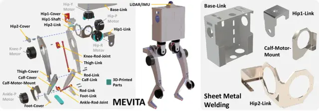
MEVITA Biped
$630090 stars on GitHub. MEVITA is an open-source bipedal robot designed to be assembled entirely from e-commerce components — sheet metal parts, machined elements, and off-the-shelf actuators — without access to specialized manufacturing. A sister project to MEVIUS (quadruped), MEVITA extends the approach to two-legged locomotion research. Published at IEEE conference proceedings with accompanying arXiv paper. Source: https://github.com/haraduka/mevita The robot has 10 degrees of freedom across two legs (5 DOF per leg: hip yaw, hip roll, hip pitch, knee pitch, ankle pitch), driven by CubeMars AK70-10 and AK10-9 V2.0 brushless actuators. All meshes are provided for full 3D-printable structural parts. A Livox LiDAR provides depth sensing for environment mapping. MEVITA runs ROS1 with reinforcement learning policies trained in Isaac Gym (leggedgym framework). The two-phase training pipeline first learns stable walking, then fine-tunes with varied friction and command distributions. Motor control uses CAN bus via RUBIK LINK V2.0 adapter. Hardware: 10× CubeMars AK70-10/AK10-9 brushless actuators, RUBIK LINK V2.0 CAN interface, Livox LiDAR, Intel RealSense T265. Open source under MIT license. --- Install Notes MEVITA has the same hardware requirements as MEVIUS. It requires a CAN bus interface** (e.g., PEAK PCAN-USB) connected to the Pi before will work — call first to initialize it. The actuators are quasi-direct-drive motors, not hobby servos. See the MEVITA hardware guide for compatible actuator specifications.
 Arm Robots
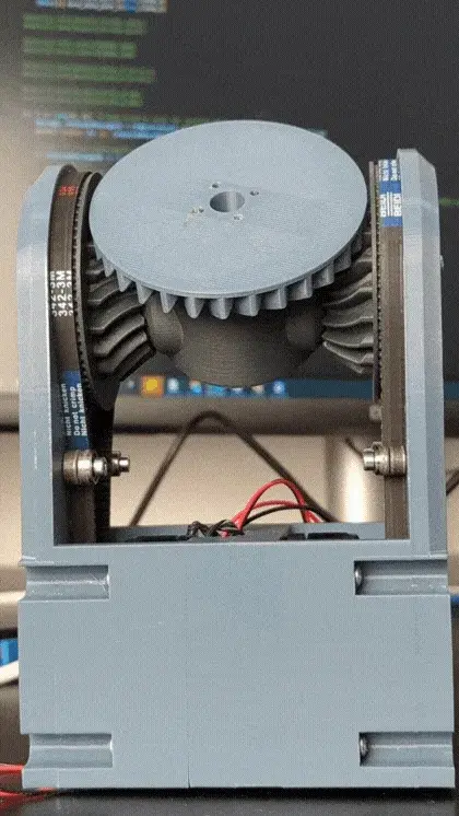
Differential Robot Wrist
Differential Robot Wrist A 2-DOF differential bevel-gear wrist mechanism from Source Robotics, open-sourced as a test fixture for their future humanoid/arm robots. Two BLDC motors drive a pair of bevel gears — moving them in the same direction yields pitch, opposing direction yields yaw/roll. The differential layout keeps both motors at the joint base (not the moving end), which lowers inertia and increases payload capacity compared to a stacked serial-motor wrist. This Program is a learning entry point for the mechanism. Print the STLs, source the BLDC motors and Spectral driver, and use the Python example to spin both motors in opposite directions to test the differential motion. What you get 11 printable STLs (housing, bevels, motor holders, pulleys, shafts) BOM with motor + driver references Python example using Source Robotics' library over slcan / CAN Hardware 2× BLDC motors (gimbal/medium-sized) with hall sensors or magnetic encoders 2× Spectral micro BLDC driver boards (CAN, from Source Robotics) CAN-USB adapter (slcan compatible, e.g. CANable) M3 fasteners, GT2 belts, magnets for the magnetic encoders 3D printer (PLA or PETG fine for the test fixture) Source Original design: Source-Robotics/Differential-robot-wrist by PCrnjak (Petar Crnjak). MIT licensed. Driver calibration: Spectral BLDC docs > ⚠️ This is the upstream author's own caveat: the mechanism is a test fixture, not a finished product. Expect to tune motor parameters and re-print parts as you iterate.
 other-robots
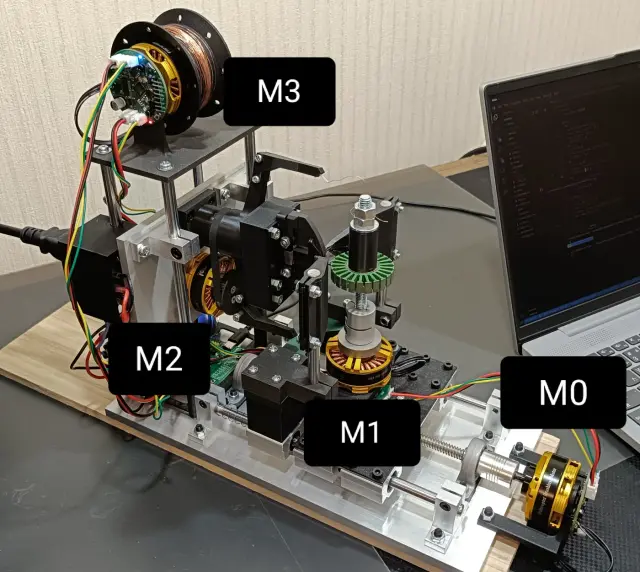
Winder — BLDC Motor Winding Machine
Automated 4-axis stator winding
Browse by type
Browse by hardware
Browse by difficulty